


The connection structure of American standard gate valves should comply with American standards (such as ASME, API, etc.), and their design and manufacturing should meet the sealing performance, strength, and installation convenience under different working conditions. The following are common connection structure types, characteristics, and related standards for American standard Gate valves:
1、 Flanged Connection
The most widely used connection method, suitable for valves ranging from DN15 to DN2000+, available in integral flanges and butt welded flanges.
1. Flange standards
Following ASME B16.5 (Steel Pipe Flanges), API 605 (Large Diameter Flanges), etc., pressure ratings include Class 150, 300, 400, 600, 900, 1500, 2500 (corresponding to maximum working pressure at different temperatures).
Flange types: plate flat welding flange (PL), neck flat welding flange (SO), neck butt welding flange (WN, preferred for high pressure), socket welding flange (SW, small diameter high pressure), threaded flange (TH, with threaded pipeline), etc.
2. Form of sealing surface
RF (Raised Face): The most commonly used, with the sealing surface 1.5~2mm higher than the flange surface, equipped with non-metallic or metal composite gaskets, suitable for medium and low pressure (Class 150~600), non corrosive media.
Ring Type Joint (RTJ): The sealing surface is a V-shaped groove, equipped with metal octagonal or elliptical gaskets, with strong sealing performance, suitable for high pressure and high temperature (Class 600+), flammable, explosive or toxic media (such as refining and chemical industry).
FF (Flat Face): The sealing surface is flush with the flange surface and is only used for low-pressure water or air pipelines (Class 150 or below), with rubber gaskets.
Concave convex surface (MFM)/mortise and tenon surface (TG): rarely used in gate valves, commonly seen in Globe valves, etc., it limits gasket displacement through concave convex or mortise and tenon structures, suitable for media that are prone to leakage.
3. Bolt connection
The material of the bolts should match the working conditions (such as A193-B7 for high temperature and A194-8 for stainless steel flanges), and the quantity and specifications of the bolts should follow the standards (such as ASME B16.5). When tightening, they should be symmetrically and evenly tightened to avoid flange deformation.
2、 Threaded Connection
Suitable for small caliber valves (DN15~DN50), compact structure, easy installation, but not suitable for high-pressure, vibration or high temperature applications.
1. Thread standard
Following the ASME B1.20.1 pipe thread standard, commonly used are NPT (taper pipe thread) or NPSM (parallel pipe thread, with sealing material).
NPT threads have inherent sealing properties and achieve sealing through thread deformation. It is necessary to wrap PTFE tape or apply thread sealant to enhance the sealing.
2. Structural characteristics
Both ends of the valve are machined with internal or external threads and directly connected to the pipeline threads without the need for gaskets.
Disadvantages: Leakage is easily caused by thread deformation under high pressure, and disassembly may damage the threads, making it unsuitable for frequent disassembly.
3、 Welded Connection
By welding and fixing with pipelines, it has excellent sealing performance and is suitable for high temperature and high pressure, highly toxic or radioactive media. It can be divided into butt welding and socket welding.
1. Butt Weld (BW) connection
Structure: The two ends of the valve are straight pipe sections with grooves, which are welded to the pipeline (full penetration welding is required), following the ASME B16.25 butt welding end standard.
Applicable: For pipelines above DN50, especially under high-pressure conditions (such as Class 900+), it can reduce stress concentration and avoid cracking in the welding heat affected zone.
2. Socket Weld (SW) connection
Structure: The valve end is a socket hole, and the pipe is inserted and corner welded. It is suitable for small diameters below DN50 to avoid the difficulty of full penetration welding. The height of the weld seam needs to be controlled (not less than the thickness of the pipe wall).
Attention: The groove needs to be cleaned before welding, and non-destructive testing (such as magnetic particle or penetrant testing) should be carried out after welding to prevent defects such as porosity and cracks.
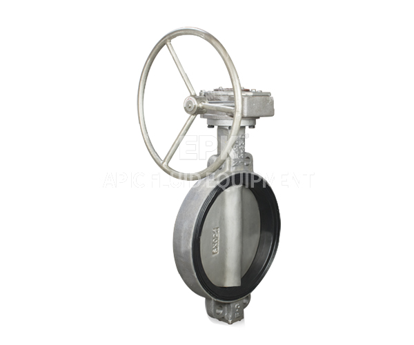
4、 Other special connection structures
1. Wafer type connection
Less commonly used for gate valves (gate valves have a large weight and rely on pipeline flange clamping for clamping), occasionally seen in small-diameter lightweight gate valves, where the valve is clamped by two flanges and the bolt is fixed through the ear of the valve body.
2. Extended Stem Connection
When the valve is installed deep underground or in a sandwich, an extension rod needs to be installed to extend the operating mechanism to the ground through a coupling or gearbox for remote operation. It is commonly used in oil pipelines or underground pipe networks.
3. Special working condition connection
High temperature expansion joint compensation: In high-temperature pipelines, metal expansion joints may be installed between valves and pipelines to compensate for thermal displacement and avoid damage to the connection structure due to additional stress.
High pressure self tightening seal: Some ultra-high pressure gate valves (such as Class 2500+) adopt a self tightening seal structure (such as lens gasket), which uses medium pressure to assist sealing and reduce bolt load.
5、 Selection criteria for connection structure
Operating parameters: pressure (Class rating), temperature (material temperature resistance), medium characteristics (corrosiveness, toxicity, flammability and explosiveness).
Installation convenience: Threaded connections are suitable for quick installation of small diameters, welded connections are suitable for permanent fixation, and flange connections are easy to disassemble and maintain.
Standard compliance: It must comply with the standards specified in the project (such as API 600 gate valves requiring flange connections to follow ASME B16.5).
Cost and maintenance: Flanged connections have high costs but are easy to maintain, welded connections have high one-time investment but the best sealing performance, threaded connections have the lowest cost but limited applicability.
summarize
The connection structure of American standard gate valves is centered around flange connections (covering the entire diameter range and adapting to working conditions through different sealing surfaces), supplemented by threaded connections (small diameter) and welded connections (high pressure and high temperature). When designing, it is necessary to strictly follow ASME, API and other standards to ensure that the sealing cover, bolts, welding process and working conditions are matched, while also considering installation convenience and long-term reliability.
This website uses cookies to ensure you get the best experience on our website.

Comment
(0)